GAE Graphics Software Products and PLOT-10 Compatibility
Galaxy Advanced Engineering, Inc. presents a migration bridge for callable PLOT-10 routines within your
existing FORTRAN program via its high level FORTRAN graphics library Language which is called UGL.
UGL is a Scientific Graphics Subroutine Library for any computing system such as Main, Micro and Mini-Computers with its given
Operating System. UGL presently supports hardware such as HP/UX, SUN/SOLARIS, Alpha/OpenVMS, VAX/VMS, LINUX,
SGI/IRIX and Window95/98/2000 and NT or DOS
UGL-GRAPHICS was developed to provide a migration path with a
CA-DISSPLA,
GKS,
CalComp,
PLOT88,
and DIGLIB (from Lawrence Livermore Lab.) graphics interface in the PC and VAX as well as UNIX environment and provides the same high graphics standards found on the main frames using the above graphics libraries. The most common subset of CA-DISSPLA routine (more than %95) and rest of the mentioned graphics libraries are supported directly and any particular ones may be provided upon request. If the users have an existing code using any of these graphics library routines within them, they do not have to change their calls. The bridge that are built with UGL - GRAPHICS library of Galaxy advanced Engineering, Inc. will distinguish these routines and maps them to its own routine against these calls for direct porting of the user code to its new environme
nt supported by UGL-GRAPHICS.
What is PLOT-10?
Plot 10 is a collection of subroutines developed by Tektronix Inc.for use with Tektronix graphics terminals. The routines can be
called by a user's FORTRAN program to enable the user to obtain high quality graphicimages on Tektronix and Tektronix-compatible terminals (including a properly
configured X-windows xterm).
Currently, many graphics terminals are raster scan devices and are similarto a television's CRT. The screen is scanned continuously from top to bottom,and
individual picture elements ("pixels") of phosphor may bechosen for illumination by firing an electron beam at the pixel location.An image is built from suitable
patterns of illuminated pixels so thatpoints, lines, and surfaces can be recognized. The graphics terminal memorykeeps track of which pixels should be activated with each
pass of the electronbeam. In the case of a computer terminal with a raster scan device, theadvantages include speed enough to enable animation of images, and
thepossibility of different levels of gray or color at each pixel. The disadvantageis that picture resolution is not very high. Since lines are formed byactivation of adjacent
elements (or cells), most lines other than horizontalor vertical show evidence of "aliasing," a jagged or stair-caseappearance.
Plot 10 was developed in the 70's, before electronic memory was so inexpensive.Instead of using raster scan screens, the graphics terminals produced by
Tektronix were "storage tube" devices. The back of the screenwas coated with a phosphor, and instead of a beam that continuously scannedthe screen, the
storage tube has an image drawn by an electron beam onlyonce, and then electronic means are used to insure that the brightenedphosphor persists. An advantage is very
high resolution of the resultantimages that are "flicker-free", but images can not be animatedbecause the screen can not be selectively erased. Color is also a difficulty.However, since extensive electronic memory was not necessary, this typeof device became a standard for graphics. Plot 10 has since been enhancedto operate
with other more sophisticated display devices, but it was designedfor this type of simple storage tube device. It is now sort of a "lowestcommon denominator"
graphics standard.
The Tektronix terminals were designed so that the basic controllable operationswere to move the aim of the electron beam, to turn the beam
on and off,and to erase the entire screen. Part of Plot 10 is concerned with sendingspecial characters (called an escape sequence) from the host computer tocontrol these
basic terminal functions. In addition, Plot 10 provides higherlevel functions such as the means to scale, rotate, clip and label graphicimages.
For purposes of controlling the location of the beam's aim, the rectangularscreen has 1024 addressable locations (0-1023) in the horizontal x direction,and 780 addressable locations (0-779) in the vertical y direction. (Theorigin is in the lower left hand corner of the screen.)
The Tektronix terminals can be used by users to generate graphics withtheir FORTRAN programs by calling Plot 10 subroutines to perform specificfunctions.
When the user's program is executed, the Plot 10 library ofroutines is linked to the user's compiled FORTRAN code. The Plot 10 User'sManual describes all of the functions.
The following describes some ofthe functions.
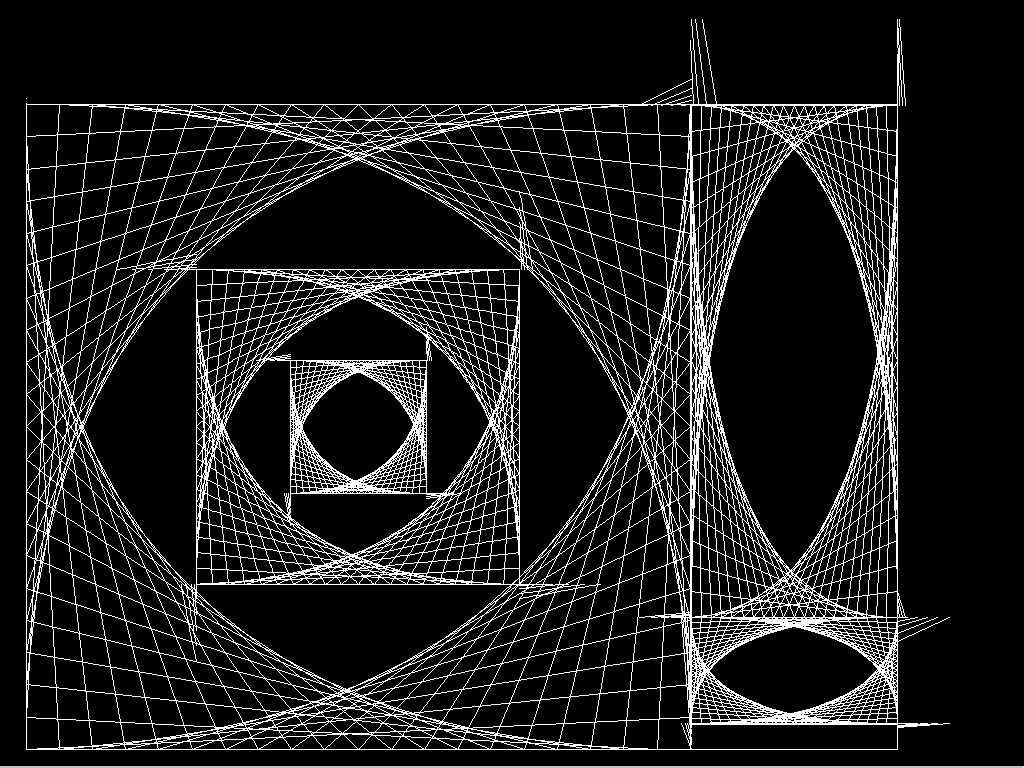
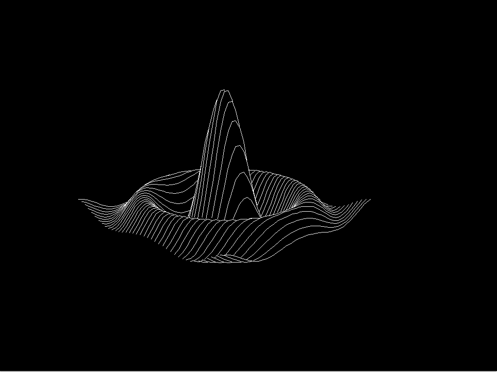
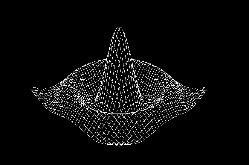
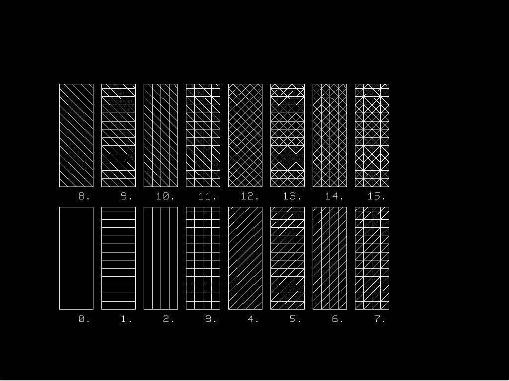
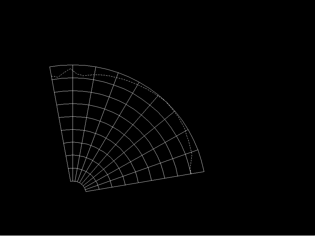
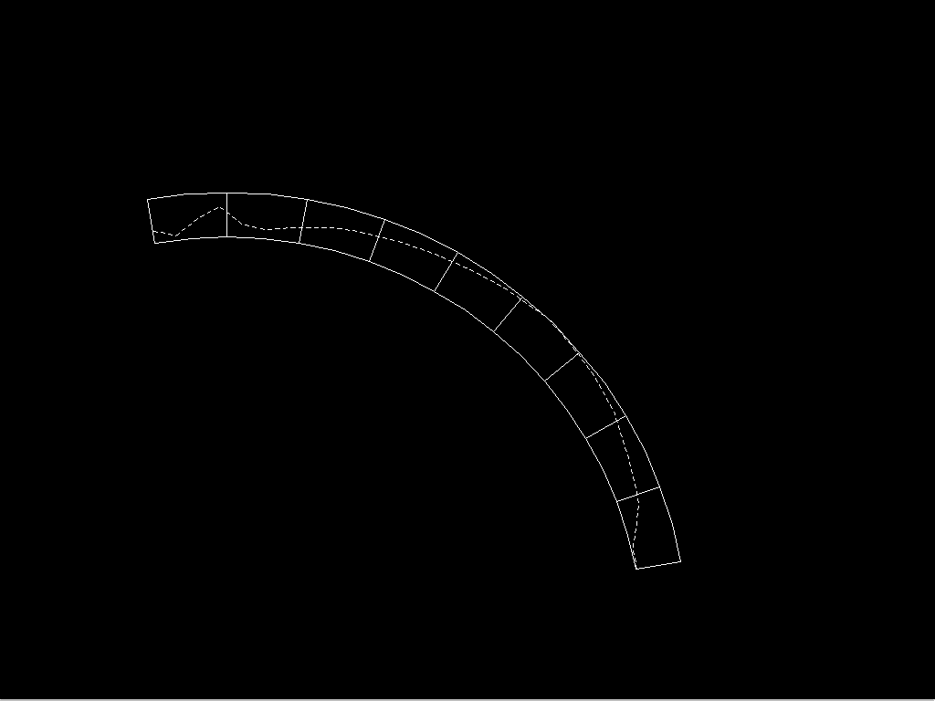
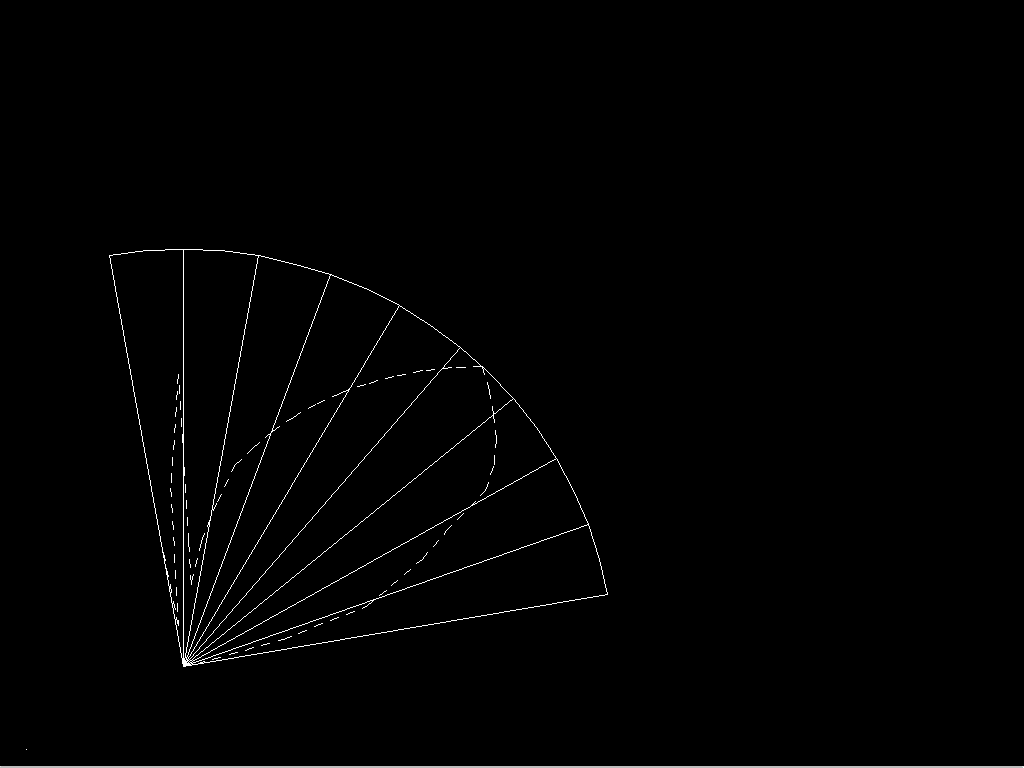
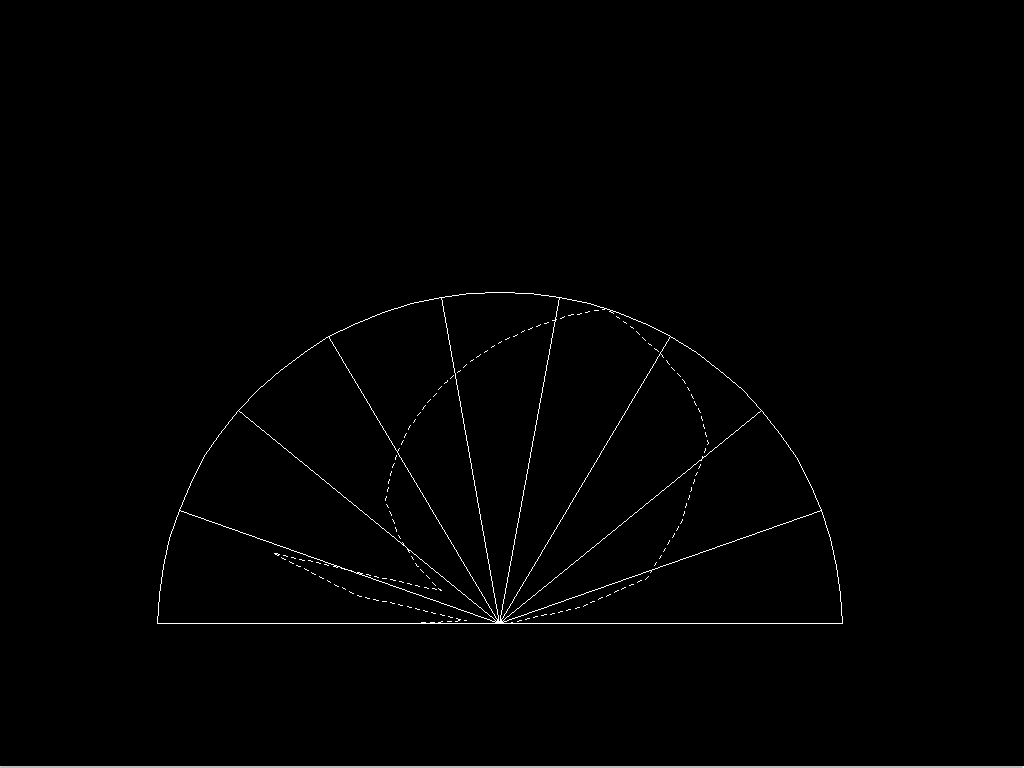
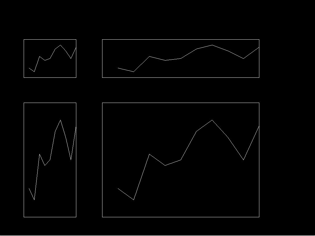
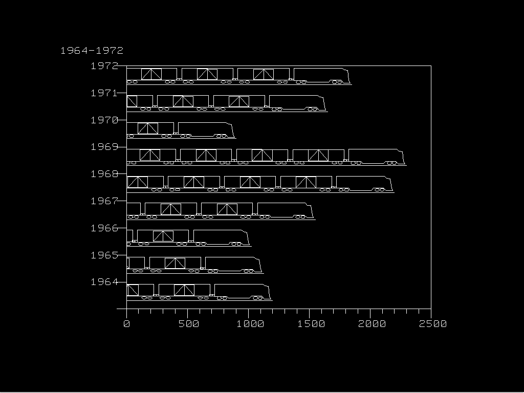
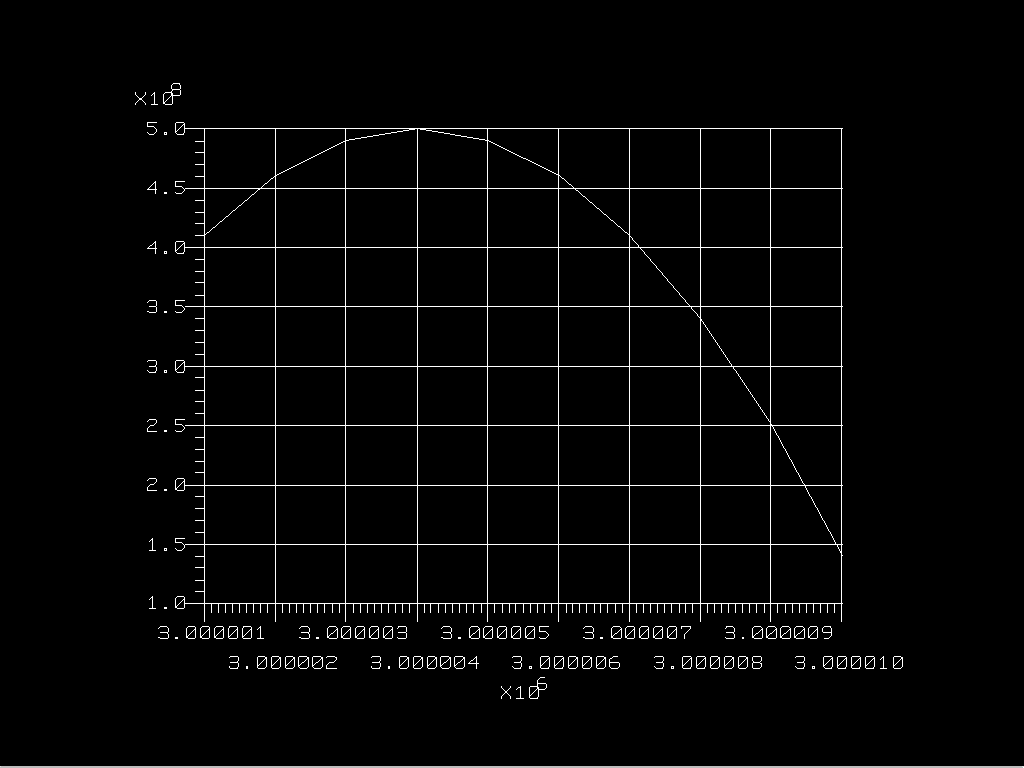
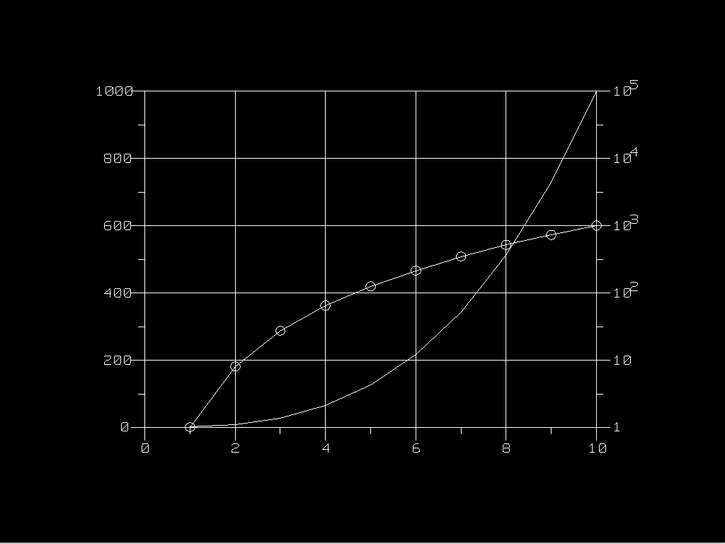
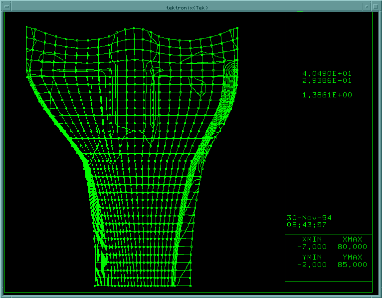
The following are some examples of plots that are generated by UGL - PLOT-10 bridge using PURE PLOT-10 SOURCE codes.